
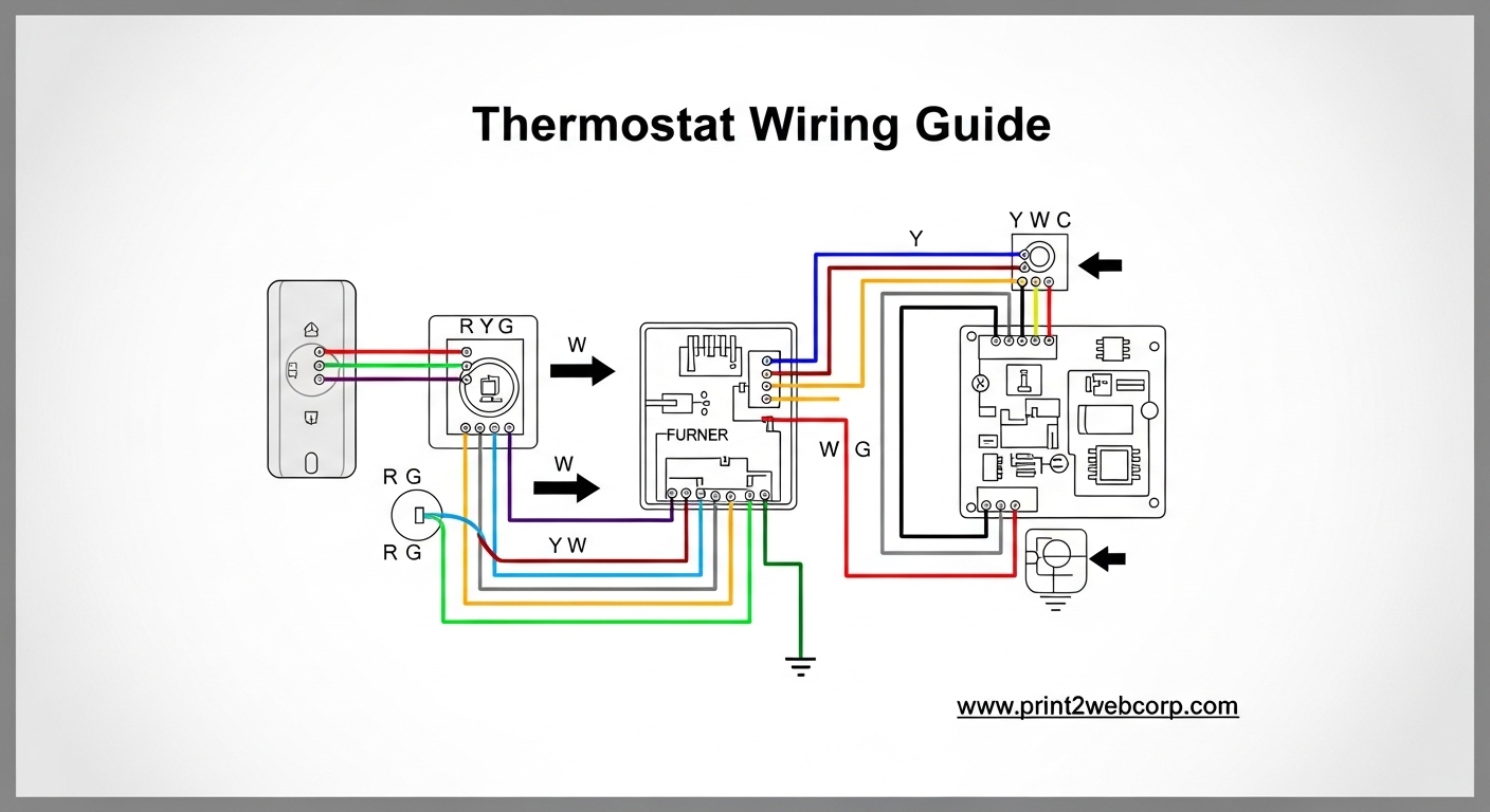
If you’re staring at a bundle of colored wires behind your thermostat and feeling overwhelmed, you’re not alone. Thermostat wiring confuses many homeowners, but understanding these low-voltage connections is essential for any DIY installation or replacement project. This guide breaks down everything you need to know about thermostat wiring, from wire color codes to step-by-step installation instructions.
Thermostat wiring is a low-voltage (24V) system that connects your thermostat to your HVAC equipment. These wires act as switches that complete circuits between the power source and various components like your furnace, air conditioner compressor, and blower fan. Unlike standard electrical wiring, thermostat wiring carries minimal voltage and is safe for most homeowners to work with—provided you follow proper safety procedures.
In this comprehensive guide, you’ll learn the standard wire color codes, what each terminal does, how to wire different types of HVAC systems, and troubleshooting tips for common issues. Whether you’re installing a smart thermostat or replacing an old mechanical one, understanding thermostat wiring will save you time, money, and potential headaches.
Understanding Thermostat Wiring Basics
Before diving into specific wire colors and terminals, it helps to understand how thermostat wiring actually works. Your thermostat is essentially a switch that controls the flow of low-voltage electricity from a transformer in your HVAC system to various relays and contactors. When you adjust the temperature, the thermostat completes or breaks specific circuits to turn equipment on or off.
The 24V transformer, typically located in your furnace or air handler, steps down your standard household voltage (120V or 240V) to a safe 24 volts. This low voltage travels through the thermostat wires and powers the control circuits in your HVAC equipment. Because this is low-voltage wiring, you don’t need to worry about electrical shock when working with these wires—after you’ve turned off the power at the source.
Proper thermostat wiring ensures reliable communication between your thermostat and HVAC system. Incorrect wiring can prevent your system from operating, cause components to run at the wrong time, or in rare cases, damage sensitive electronics. That’s why understanding the basics before starting any installation project is so important.
Thermostat Wire Color Code Guide
Thermostat wire colors follow a industry-standard convention that makes identification easier. However, keep in mind that previous homeowners or contractors may not have followed these standards—always label wires by the terminal they were connected to, not by their color. Here’s the complete breakdown of standard thermostat wire colors and their functions:
R Wire (Red) – 24V Power
The red wire provides constant 24V power from the transformer to your thermostat. This is the primary power source that allows your thermostat to operate. Every low-voltage thermostat needs at minimum an R wire connected to function. Some systems have separate Rc (cooling power) and Rh (heating power) terminals, which both use red wires.
C Wire (Blue or Black) – Common Wire
The C wire, typically blue or black, completes the circuit back to the transformer. While traditional thermostats could operate without a C wire (using batteries or “power stealing” from other wires), modern smart thermostats require a continuous power source that only a C wire provides. If you’re upgrading to a smart thermostat and don’t have a C wire, you may need an adapter or professional installation.
W Wire (White) – Heating
The white wire connects to the W terminal and controls your heating system. When your thermostat calls for heat, it completes the circuit between R and W, sending power to your furnace’s heating relay or control board. This wire is essential for any system with a heating component—furnaces, boilers, and heat pumps in heating mode all rely on the W wire.
Y Wire (Yellow) – Cooling
The yellow wire connects to the Y terminal and controls your air conditioning compressor. When cooling is needed, the thermostat connects R to Y, activating the compressor contactor. For systems with a compressor and a separate condenser fan, the Y wire typically controls both simultaneously.
G Wire (Green) – Fan
The green wire connects to the G terminal and controls your air handler’s blower fan. When you set your thermostat to “fan on” mode, it completes the R-to-G circuit, running the fan continuously. During normal heating or cooling cycles, many systems automatically activate the fan through other control wires (W or Y) rather than the G wire.
O Wire (Orange) – Reversing Valve for Cooling
The orange wire connects to the O terminal and is used with heat pumps. It controls the reversing valve in the cooling direction. When your heat pump switches to cooling mode, the O wire energizes the reversing valve, changing the refrigerant flow so the outdoor unit releases heat and the indoor unit absorbs it.
B Wire (Brown or Blue) – Reversing Valve for Heating
The B wire serves a similar function to the O wire but energizes the reversing valve in the heating direction. Some heat pump systems use O for cooling mode, while others use B for heating mode—rarely both. Most modern systems use the O terminal configuration, making B wire increasingly uncommon in residential installations.
Rc vs Rh – Separate Cooling and Heating Power
Some systems have separate transformers for heating and cooling, resulting in two red wires: Rc (red cooling) and Rh (red heating). In most single-transformer systems, these terminals are jumpered together at the thermostat, and a single red R wire powers both functions. If you have both Rc and Rh wires, do not jumper them—connect each wire to its corresponding terminal.
Thermostat Terminal Functions Explained
Understanding what each terminal does helps you troubleshoot problems and verify correct wiring. When your thermostat activates heating, cooling, or fan mode, it completes specific circuits that send power through particular wires. Let’s explore what happens when each terminal connection is made.
R to W Circuit – Heating Activation
When you set your thermostat above the room temperature, it completes the circuit between R and W. This sends 24V power through the white wire to your furnace’s heating control, activating the burners, heating elements, or heat strips depending on your system type. The blower fan typically activates shortly after to distribute warm air throughout your home.
R to Y Circuit – Cooling Activation
Setting your thermostat below room temperature completes the R-to-Y circuit. Power flows through the yellow wire to the compressor contactor, engaging your outdoor condensing unit. In most systems, this also activates the indoor blower fan to circulate cooled air. The compressor and outdoor fan run until the thermostat is satisfied.
R to G Circuit – Fan Activation
When you select “fan on” mode at your thermostat, the R-to-G circuit is completed. The green wire sends continuous power to the blower fan relay, causing the fan to run constantly regardless of heating or cooling demands. This is useful for air circulation but typically increases energy consumption compared to “auto” fan mode.
C Wire – Common Return Path
The C wire provides a return path to the transformer, completing the electrical circuit. Traditional battery-powered thermostats didn’t require this wire because they used batteries for power and only needed momentary connections to trigger HVAC functions. Modern smart thermostats with Wi-Fi, touchscreens, and backlit displays require continuous power, making the C wire essential for reliable operation.
O/B Terminal – Heat Pump Reversing Valve
Heat pumps can both heat and cool your home by reversing refrigerant flow. The reversing valve controls this direction, and the O or B wire activates it. Most manufacturers use the O terminal configuration, where the reversing valve energizes for cooling mode. Some older systems use B, which energizes for heating mode. Your thermostat documentation will specify which to use for your heat pump.
Thermostat Wiring in 2026
Modern thermostats have evolved beyond simple mechanical switches to include Wi-Fi connectivity, learning algorithms, and energy-saving features. Despite these advancements, the basic wiring principles remain unchanged. Whether you’re installing a basic programmable thermostat or a high-end smart model, you’ll connect the same wires to the same terminals.
Smart thermostats require a C wire for continuous power. Without it, you may experience battery drain issues, connectivity problems, or unreliable performance. Many newer homes have a C wire installed, but older homes often lack this wire. If you’re missing a C wire, options include running a new wire, using a C-wire adapter (sometimes called a “power extender kit”), or hiring a professional to install one.
Another consideration in 2026 is compatibility with multi-stage and dual-fuel systems. These advanced HVAC configurations require additional wires (W2, Y2, E, Aux) that must be properly connected to ensure all heating and cooling stages operate correctly. Always verify your new thermostat is compatible with your system type before purchasing.
Heat Pump Wiring and Special Systems
Heat pumps require additional wiring beyond standard heating and cooling systems. Because heat pumps both heat and cool, they need a reversing valve wire (O or B) to switch between modes. The O wire is most common and energizes the reversing valve for cooling. Some systems use B, which energizes for heating—rarely both, so you’ll use one or the other, not both simultaneously.
Emergency heat is another heat pump-specific function. When outdoor temperatures are extremely cold, your heat pump may struggle to extract enough heat from the outside air. The E or Aux terminal connects to supplemental electric heat strips that activate during defrost cycles or when you manually select emergency heat mode. This wire is typically connected to the same terminal as W2 (second-stage heating) in many installations.
Two-stage heating and cooling systems use W2 and Y2 wires respectively. These activate when first-stage heating or cooling isn’t sufficient to meet demand. For example, a two-stage furnace might run at low capacity initially (activated by W) and switch to high capacity (activated by W2) if the temperature drops significantly below setpoint. Two-stage air conditioners work similarly, with Y controlling the first stage and Y2 controlling the second stage.
Dual-transformer systems have separate power sources for heating and cooling. These systems have both Rc and Rh wires, which connect to separate 24V transformers—one in the furnace for heating, one in the air handler for cooling. If you have both wires, connect each to its matching terminal and don’t jumper them together. Some thermostats have a single R terminal with a factory-installed jumper—remove this jumper if you have separate Rc and Rh wires.
How to Wire a Thermostat: Step-by-Step Guide
Installing or replacing a thermostat is a manageable DIY project when you follow proper procedures. This step-by-step guide walks you through the entire process, from removing your old thermostat to testing your new installation.
Step 1: Turn Off Power
Before touching any wires, turn off power to your HVAC system at the source. This is typically a switch mounted on or near your furnace or air handler. Flipping the breaker at your electrical panel is another option. While low-voltage thermostat wiring won’t shock you, shorting wires together can damage your HVAC equipment’s control board. Take this step seriously—it’s the most important safety precaution in the entire process.
Step 2: Remove the Old Thermostat
Most thermostats pull straight off the wall plate after releasing a locking mechanism or removing screws. Some have a button or latch that releases the unit. Once removed, you’ll see the wires connected to terminals on the wall plate. Don’t disconnect anything yet—you’ll label them first.
Step 3: Label Wires by Terminal
This is the most critical step. Before disconnecting any wires, label each one according to the terminal it’s connected to. Use the labels that came with your new thermostat, or make your own with masking tape and a marker. Label wires “R,” “W,” “Y,” “G,” “C,” etc., based on the terminal they’re connected to—not by their color. This is especially important in older homes where previous owners may have used non-standard colors.
Step 4: Take a Photo
Before disconnecting anything, take a clear photo of the wiring with your phone. This provides a reference in case you forget which wire went where, or if labels fall off during installation. Many HVAC technicians recommend this as standard practice—it’s saved countless homeowners from confusing wiring configurations.
Step 5: Disconnect Wires
With wires labeled and photo taken, you can safely disconnect them from the old thermostat’s wall plate. Most thermostat wires are held in place by small screws—loosen these with a small screwdriver and gently pull the wires free. Some newer systems use push-in terminals that require releasing a small tab or button to remove the wire.
Step 6: Remove the Wall Plate
Unscrew and remove the old wall plate from the wall. You’ll now see a hole where the wires come through. Keep the wires from slipping back into the wall by wrapping them around a pencil or gently taping them to the wall. Losing wires inside the wall can turn a simple project into a frustrating fishing expedition.
Step 7: Install the New Wall Plate
Thread the wires through the opening in your new thermostat’s wall plate, then screw the plate securely to the wall. Use a level to ensure the plate is straight—a crooked thermostat looks unprofessional and may affect operation in some models. If your new plate doesn’t completely cover paint marks from the old plate, you may need to touch up the paint.
Step 8: Connect Wires to Terminals
Connect each labeled wire to the matching terminal on your new thermostat. Refer to your labels and the photo you took earlier if needed. Most wires connect by loosening a terminal screw, inserting the bare wire end, and tightening the screw. Some models use push-in terminals that accept wires without screws. Ensure wire ends are stripped to the proper length (usually about 1/4 inch) and not frayed or damaged.
Step 9: Install the Thermostat
Once all wires are connected, attach the thermostat unit to the wall plate according to the manufacturer’s instructions. This usually involves aligning the unit with the plate and pressing firmly until it clicks into place. Some models require screws to secure the unit to the plate.
Step 10: Restore Power and Test
Turn power back on to your HVAC system. Your thermostat should power up within a few seconds. Test heating by setting the temperature several degrees above room temperature. Listen for your furnace to activate and feel for warm air from vents within a few minutes. Test cooling similarly by setting the temperature below room temperature and verifying that the air conditioner starts. Finally, test the fan by setting it to “on” mode and verifying continuous blower operation.
Troubleshooting Common Thermostat Wiring Issues
Even with careful installation, issues can arise. This section covers common thermostat wiring problems and their solutions, helping you diagnose and fix issues without calling a professional.
Wire Colors Don’t Match the Standard
If your wires don’t match standard colors, don’t panic. Previous owners may have used whatever wire was available during installation or repairs. This is why labeling by terminal (not color) during removal is so important. If you didn’t label your wires and are unsure what they do, you may need to trace them back to your HVAC equipment. This typically requires removing the access panel on your furnace or air handler and noting which terminal each wire connects to at the equipment end.
Thermostat Won’t Power On
If your new thermostat doesn’t power on after installation, first verify that power is turned on at your HVAC system. Check the breaker and any emergency switches near your furnace. If power is confirmed and the thermostat still won’t turn on, you may be missing a C wire for smart thermostats that require continuous power. Battery-powered models may simply need fresh batteries. For hardwired models without a C wire, some can work without it but may experience reduced functionality.
Heating or Cooling Won’t Activate
If heating or cooling doesn’t respond when you adjust the temperature, first check that the correct wire is connected to the W or Y terminal. Loose connections at either the thermostat or the HVAC equipment can prevent proper operation. Verify that the wire is securely fastened and making good contact. If connections are correct, the issue may be with your HVAC equipment rather than the thermostat wiring—faulty relays, blown fuses, or broken wires can all prevent system activation.
Fan Runs Constantly
If your fan runs continuously regardless of thermostat settings, check the G wire connection. A loose G wire that’s making intermittent contact can cause the fan to run unexpectedly. Some thermostats have a “fan” setting that overrides programming—verify you haven’t accidentally set the fan to “on” mode. If neither issue is the cause, you may have a stuck fan relay at your HVAC equipment that requires professional repair.
Heat Pump Won’t Switch Modes
If your heat pump won’t switch between heating and cooling, check the O or B wire connection. Verify that you’ve connected the correct wire for your system—most use O, but some use B, and rarely both. Check your heat pump’s documentation to confirm which terminal it requires. Also verify that your thermostat is configured correctly for heat pump operation in its setup menu.
When to Call a Professional
While many thermostat wiring issues are DIY-friendly, some situations require professional expertise. Complex systems like dual-fuel setups, communicating thermostats that use only a few wires, or systems with proprietary wiring schemes should be handled by qualified HVAC technicians. If you’ve tried troubleshooting without success, or if you’re uncomfortable working with electrical components even at low voltage, there’s no shame in calling a professional. Improper wiring can damage expensive equipment and may void warranties.
Frequently Asked Questions
What is the correct wiring for a thermostat?
The correct thermostat wiring connects specific wires to their matching terminals: R (red) for 24V power, C (blue/black) for common return, W (white) for heating, Y (yellow) for cooling, G (green) for fan, and O/B (orange/brown) for heat pump reversing valve. Always label wires by the terminal they connect to, not by color, as previous installations may have used non-standard colors. The most basic thermostat needs at minimum an R wire and either W (heating only) or Y (cooling only).
What are the color codes for thermostat wires?
Standard thermostat wire color codes are: Red (R) for 24V power, White (W) for heating, Yellow (Y) for cooling, Green (G) for fan, Blue or Black (C) for common, Orange (O) for heat pump reversing valve cooling, and Brown (B) for heat pump reversing valve heating. Some systems use separate Rc (red cooling) and Rh (red heating) wires. However, always verify wiring by terminal labels rather than color, as previous installations may not have followed standard conventions.
What does each thermostat wire do?
The R wire supplies 24V power to the thermostat, while the C wire completes the circuit back to the transformer. The W wire activates heating when connected to R, the Y wire activates cooling, and the G wire controls the fan. Heat pumps use O or B wires to control the reversing valve that switches between heating and cooling modes. Additional wires like W2 and Y2 control second-stage heating and cooling for more advanced systems.
Why is the C wire important for smart thermostats?
The C wire provides a continuous return path for power, allowing smart thermostats to maintain consistent operation without relying on batteries or intermittent power stealing from other wires. Smart thermostats with Wi-Fi, touchscreens, and backlit displays require constant power that only a C wire can reliably provide. Without a C wire, smart thermostats may experience battery drain issues, connectivity problems, or unreliable operation. If your home lacks a C wire, options include running new wire or using a C-wire adapter.
What happens if you wire a thermostat incorrectly?
Incorrect thermostat wiring can prevent your HVAC system from operating properly. Common issues include heating or cooling not activating, the fan running at wrong times, or the thermostat not powering on. In rare cases, incorrect wiring can damage sensitive electronics in your HVAC equipment or cause the system to operate inefficiently, increasing energy bills. The most important prevention is labeling wires by terminal before disconnecting your old thermostat and taking a photo as reference.
Conclusion
Understanding thermostat wiring empowers you to install, replace, and troubleshoot your home’s temperature control system with confidence. Whether you’re upgrading to a smart thermostat or simply need to replace a malfunctioning unit, the knowledge you’ve gained from this guide will help you complete the project safely and correctly. Remember to always label wires by terminal, take photos before disconnecting, and turn off power before beginning any work.
For straightforward replacements in homes with existing wiring, most homeowners can complete the installation in under an hour. Complex systems like dual-fuel setups, multi-stage equipment, or homes without a C wire may require professional assistance. When in doubt, consulting a qualified HVAC technician can prevent costly mistakes and ensure your system operates safely and efficiently.
Leave a Reply